

Why Do Boomerangs Come Back? The Physics Explained
Updated:
A returning boomerang comes back because its shaped wings create aerodynamic lift, while its spin and the uneven lift turn its axis through gyroscopic precession. Together, these effects curve its flight. A suitable design, a good release and the wind conditions determine how close it comes to the thrower.
How a returning boomerang works
1. Its arms act as wings
Each arm has a shaped cross-section, called an airfoil. As it moves through the air, pressure forces act on it. Lift acts perpendicular to the local airflow; drag acts against the motion. Both the boomerang’s forward movement and its rotation affect the airflow over each arm. NASA’s introduction to lift explains the underlying principle.
Lift does not always point straight up. With a boomerang spinning almost upright, much of the lift acts sideways. This sideways force bends the flight path.
2. The lift is uneven during each rotation
For a typical upright throw, the arm moving forward at the top of the rotation meets the air faster than the arm moving backward at the bottom. It generally produces more lift. Each arm passes through both positions as the boomerang spins.
This difference creates a turning effect, called torque.
3. Spin and torque change its direction
Spin gives the boomerang angular momentum. When aerodynamic torque acts across its spin axis, the direction of that axis changes. This is gyroscopic precession. The changing orientation lets the aerodynamic force keep turning the flight path.
The MIT BLOSSOMS lesson on boomerang physics demonstrates the connection between torque, angular momentum and precession. For a mathematical treatment, see Hugh Hunt’s Unspinning the boomerang.
Why does the boomerang tilt during flight?
A boomerang’s orientation changes as it travels. Many returning designs gradually tilt towards a flatter position, often called layover. This changes the direction of the aerodynamic force and how much of it supports the boomerang against gravity.
Its shape, wing angles, mass distribution, spin and release all affect this motion. The United States Boomerang Association’s flight guide gives a practical introduction to these effects. A real flight is more complex than a perfect circle at a constant speed.
Our original model: radial and arc sections
The diagrams below come from the model developed by my father and presented in the earlier version of this article. It separates the boomerang into radial and arc sections to discuss turning and changes in tilt. These terms and the numerical relationships later in this section belong to that model.
A two-arm boomerang has two physical arms. The model’s four sections are an analytical way of describing their aerodynamic roles; they are not four separate arms.

In this model, the radial sections extend outward from the centre of rotation. The arc sections run across their ends. The diagrams use these simplified sections to examine forces at different points in a rotation.
The labels “active” and “passive” describe the model’s idealised positions. On a real boomerang, airflow and aerodynamic forces change continuously.

Original model: radial sections in the active position.

Original model: arc sections in the active position.
The model describes two components of the changing orientation: turning around the flight path and changing the tilt of the spinning plane. The aerodynamic forces create torque, which changes angular momentum.
Turning around the flight path: Ω1
The original model calls the turning component the first type of precession and labels its angular speed Ω1.

In these diagrams, v is forward speed and w is spin speed. The advancing and retreating radial sections experience different airflow. Their unequal lift produces a torque that changes the direction of the spinning boomerang.
The diagrams separate the forces and rotation to make this part of the model easier to follow. They are schematic, rather than measurements of a particular throw.


Changing the tilt: Ω2
The model calls the change in the spinning plane the second type of precession, labelled Ω2. It assigns an important role to the arc sections and their angles.
Changing the tilt changes the vertical component of lift. It does not guarantee a constant upward force or a fixed time in the air: speed, orientation and aerodynamic forces all change during flight.
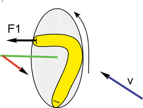

Within this simplified model, the angle of the arc sections affects the direction and strength of the tilting motion. The drawings show an aerodynamic force and the Ω2 rotation used to represent this part of the model.
For a real boomerang, the full shape and airflow must be considered together. These diagrams help explain the model; they should not be used as universal tuning instructions.
How the model combines turning and tilt
The model combines Ω1, the turning component, with Ω2, the tilting component, to describe different flight patterns.
It expresses their relationship as Ω2 = K × Ω1, where K is the ratio used in this model.
The original model associates K = 1/3 with a figure-eight pattern and K = 1/4 with an O-shaped pattern. These are model-specific values, not universal constants or guaranteed predictions for every returning boomerang.
Actual flight depends on the boomerang, the release and the moving air. Use the diagrams below as examples of the patterns described by the model, rather than exact routes or landing points.
Examples of boomerang flight paths
The original diagrams show top views. They do not show the full changes in height, speed or tilt during a flight.

Figure-eight example from the original model, viewed from above.
Figure-eight flight path
In this example, the boomerang makes a large outward loop, returns towards the launch area and continues into a smaller loop on the other side. From above, the two loops resemble an uneven figure eight.
This is one possible pattern. The precise turns, height and landing point vary with the design and the throw.
O-shaped flight path
In this example, one broad loop dominates the flight when viewed from above. The boomerang curves back towards the launch area and may finish with a slower descent.
An O-shaped path does not by itself guarantee a slow or safe return. Keep watching the boomerang and let it land if the catch is uncertain.

O-shaped example from the original model, viewed from above.
What does the physics mean for your throw?
- Follow the technique for your throwing hand. All boomerangs we sell can be used by both left-handed and right-handed throwers. Only the throwing technique differs. Follow the instructions for your dominant hand in our How to Throw a Boomerang guide.
- Give it clean spin. Rotation is part of the flight mechanism. Throwing harder alone will not correct a poor release.
- Check the release angle and wind. Start with the guidance for your model and adjust one thing at a time.
- Keep the flight area clear. Use a large, open space away from people, animals, roads and obstacles. Let an uncertain return land.
For the practical steps, read how to throw a boomerang. If yours misses the return, use our guide to why your boomerang is not coming back.
Common questions about boomerang physics
Do all boomerangs come back?
No. A returning boomerang needs a design suited to returning flight. A curved shape alone is not enough, and non-returning throwing sticks have different purposes.
Does a boomerang need wind to return?
No. Forward motion and spin create airflow over the wings even in still air. Wind changes the flight relative to the ground and where the boomerang lands.
Does it fly straight out and then reverse?
Usually it follows a curved route. The top-view diagrams above show examples of loops; they are not promises of an exact flight path.
About the original diagrams
The radial-and-arc model and its diagrams are retained from my father’s work, previously linked here at mumris.eu. This updated article adds a general introduction and separates the model’s assumptions from the wider physics explanation.

